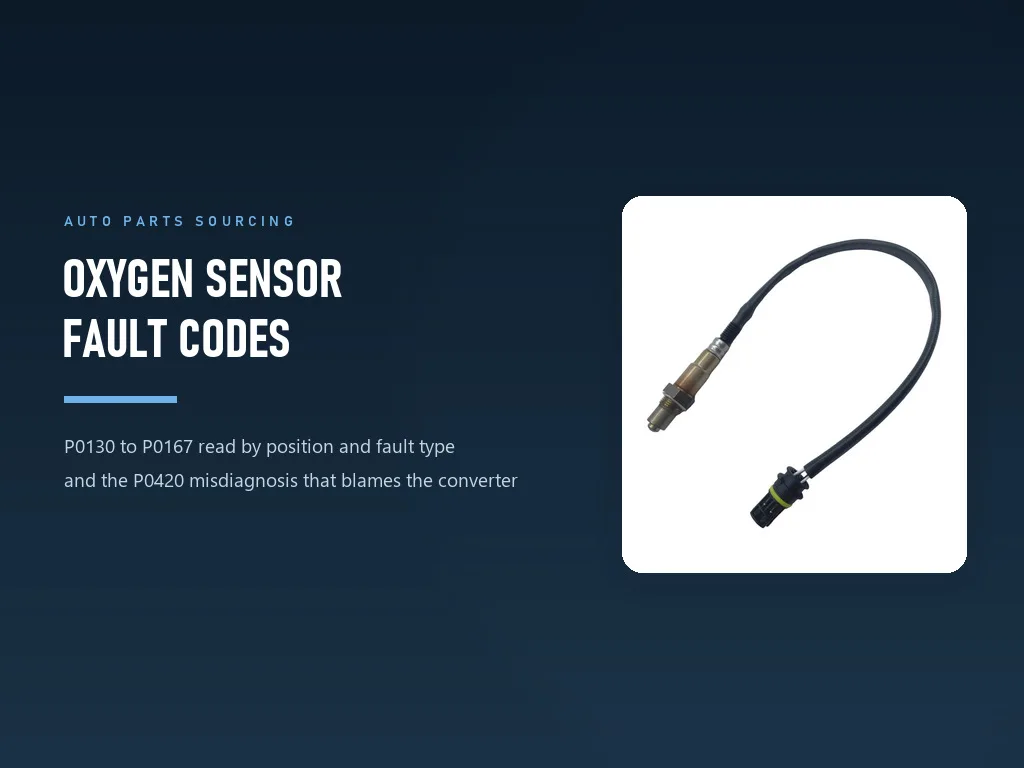
Oxygen Sensor Fault Codes: P0130-P0167 and the P0420 Misdiagnosis
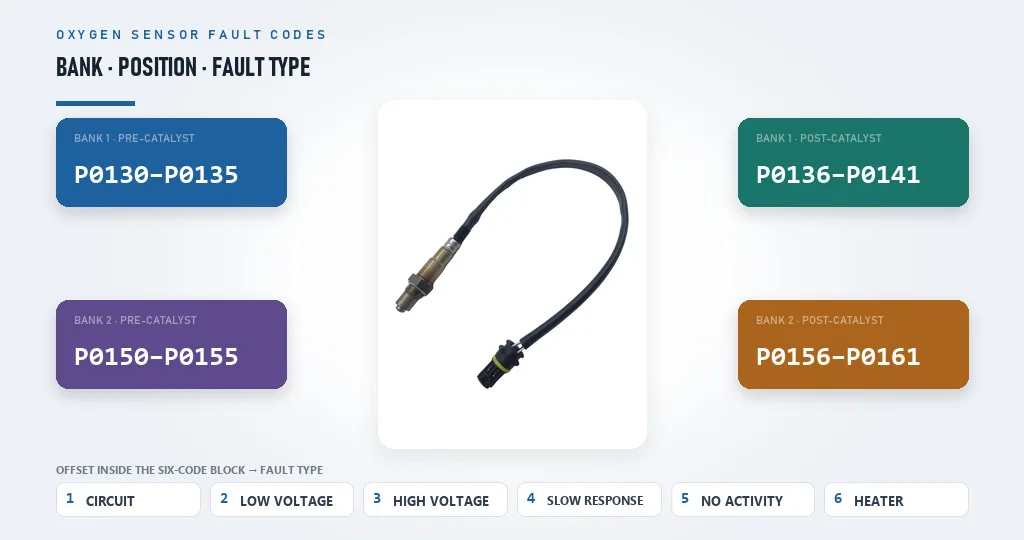 The code number is not a random reference. It carries the bank, the sensor position, and the type of fault inside four characters, which makes this one of the few code families a distributor can read without a decoder.
1. The Code Family That Converts to Parts Most Reliably
Compare two fault codes that land on a distributor's desk in the same afternoon.
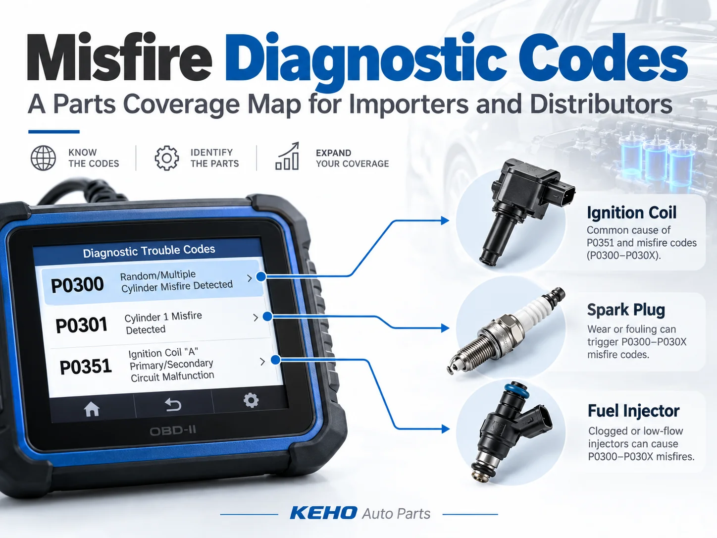
P0301 tells you cylinder 1 misfired. It does not tell you why, and the cause can sit in the ignition system, the fuel system, a vacuum leak, or the mechanical condition of the engine itself. Some of those jobs end at a compression reading and no part sale.
P0135 tells you the heater circuit in the bank 1 pre-catalyst oxygen sensor has failed. The heater and the sensing element are sealed into one assembly, so there is no version of that repair in which no part is sold.
That difference is the commercial case for understanding this code family properly. Almost every code in the range resolves to a specific sensor at a specific position, so the judgement a distributor has to supply is which sensor, and in one important case whether to sell a part at all.
Fact: KEHO has supplied auto parts to importers in 80+ countries since 1995, holding ISO/TS 16949 certification since 2012 along with CE marking and SGS third-party verification (per company data).
There is a second reason this family deserves attention. P0420 is easy to misread, and misreading it sends customers toward a repair estimate that can run into four figures for the wrong component. A distributor who can explain why earns the next enquiry. A distributor who simply confirms the customer's guess sells one converter that was never needed, if they stock converters at all, and loses the account when the light comes back on.
This guide covers how the sensor works in the terms the codes are written in, how to decode P0130 to P0167 by structure, what the catalyst monitor is actually measuring, and how to build a stock plan around code families instead of vehicle lists. The product-level question of which sensor to buy for a given application is covered in the oxygen sensor buying guide.
2. How the Sensor Works, in the Terms the Fault Codes Use
You can read the code table as a list of numbers to memorise, or you can read it as a description of how a zirconia sensor behaves when each of its failure modes arrives. The second reading is what lets a distributor answer a question the code does not cover.
2.1 The 0.2 / 0.45 / 0.8 volt window
An automotive oxygen sensor does not measure oxygen concentration directly. It compares the oxygen content of the exhaust against that of the outside air, and it does so across a thimble-shaped zirconia ceramic element coated on both sides with a thin layer of platinum [1]. The voltage it produces is non-linear and only sensitive near the stoichiometric point, which is the property that makes it useful for fuel control.
Three voltages describe the working range [1]:
- Around 0.2 V indicates a lean mixture, where oxygen remains after combustion.
- Around 0.8 V indicates a rich mixture, with little unburned oxygen left in the exhaust.
- The control setpoint sits near 0.45 V, which is where the engine control unit aims to keep the mixture, close to the 14.7:1 stoichiometric ratio that lets a three-way catalyst work properly [1].
This explains a code pattern that otherwise looks contradictory. A sensor reporting a persistent voltage below its expected range and one reporting a persistent voltage above it are both flagged as faults, because a sensor parked at either extreme is either seeing a genuinely abnormal mixture or has stopped responding to change at all.
The sensor was developed by Bosch in the late 1960s and entered production use in 1976, with Volvo being the first manufacturer to combine it with a three-way catalyst [1]. Leaded petrol is incompatible with that combination, for a reason that becomes important later: lead is a catalyst poison, and it was removed from automotive petrol precisely so catalytic converters could survive [2].
2.2 Why the heater exists, and why heater codes dominate
A zirconia sensor only begins to work effectively once it is heated to approximately 316°C (600°F) [1]. On an unheated probe, exhaust gas has to bring the element up to temperature by itself, which can take several minutes depending on ambient conditions and exhaust geometry [1]. During that window the engine runs without oxygen feedback, which is a pollution problem as much as a drivability one.
The fix was to build a heater into the sensor. The planar-style sensor that reached the market in 1990 reduced the ceramic mass and moved the heating element inside the ceramic structure, producing a probe that starts sooner and responds faster [1].
Every one of those heaters is a resistance element that carries current from a cold start and cycles for the life of the vehicle. When it fails, it fails as an open or out-of-range circuit, which is a discrete, easily detected event rather than a gradual drift. That is why heater codes occupy such a large share of oxygen sensor faults, and why they are the most dependable parts orders in the family.
2.3 Wire count as a fitment field
The wire count on a sensor is not cosmetic. It reflects how the sensor is powered and how its signal is referenced, and it has to match the vehicle.
A typical probe carries four wires: two for the lambda signal and two for heater power [1]. Some manufacturers use the metal case as the signal ground, which produces a three-wire sensor, and earlier non-heated designs used one or two wires [1].
For a distributor, the wire count belongs in the catalogue next to the OEM number. A four-wire and a three-wire sensor for the same engine may look interchangeable in a photograph and be electrically different, and the fault that follows a mismatched installation reads on a scan tool as a sensor fault. The cross reference guide covers how to hold that data in a form that survives an order desk.
3. The Code Map: P0130 to P0167 Without a Decoder Ring
Most published code lists treat each number as a separate fact to look up. The range is built on a pattern, and once the pattern is visible the list collapses into something a distributor can hold in memory.
3.1 Six codes per position, and what the offset means
The P0130 to P0167 range covers oxygen sensors on bank 1 and bank 2. Within it, each physical sensor position owns a block of six consecutive codes, and the position of a code inside its block describes the type of fault.
| Offset in the block | Bank 1 sensor 1 | Fault type |
|---|---|---|
| First | P0130 | Circuit malfunction |
| Second | P0131 | Voltage persistently low |
| Third | P0132 | Voltage persistently high |
| Fourth | P0133 | Response too slow |
| Fifth | P0134 | No activity detected |
| Sixth | P0135 | Heater circuit fault |
The same six-fault sequence repeats for the next position on the same bank, which is why P0136 to P0141 describe the bank 1 post-catalyst sensor in the same order, and why P0150 to P0155 repeat it again for bank 2 pre-catalyst [3].
Two practical consequences follow. First, the offset tells you what kind of failure to expect on the part, and the failure types behave differently in the field: a heater fault is a discrete electrical failure, while a response-too-slow code describes a sensor that still produces a signal and is drifting out of specification. Second, the code does not need to be memorised individually, because the question "which fault is this, and on which sensor" can be answered from the last digit and the block it sits in.
3.2 The code number carries the bank and the position
| Code group | Bank and sensor position | Typical commercial reading |
|---|---|---|
| P0030 to P0034 | Bank 1 heater control circuits | Heater-side fault; check the circuit, then the sensor |
| P0053 and P0054 | Heater resistance, bank 1 and bank 2 pre-catalyst | Heater fault reported by resistance rather than by circuit |
| P0130 to P0135 | Bank 1 pre-catalyst | The sensor the engine uses for fuel correction |
| P0136 to P0141 | Bank 1 post-catalyst | The sensor used to judge converter efficiency |
| P0142 to P0147 | Bank 1 third position | Used on some V-engine layouts |
| P0150 to P0155 | Bank 2 pre-catalyst | Fuel correction on the second bank |
| P0156 to P0161 | Bank 2 post-catalyst | Converter monitoring on the second bank |
| P0162 to P0167 | Bank 2 third position | Used on some V-engine layouts |
| P0420 and P0430 | Bank 1 and bank 2 converter | Converter efficiency below threshold, not a sensor fault |
| P0171, P0174, P0172, P0175 | Bank 1 and bank 2 mixture | Mixture codes derived from sensor feedback |
The distinction that matters commercially sits in the first and second rows of that table. A pre-catalyst sensor is a control input, so a fault there degrades fuel correction and produces drivability complaints that bring the vehicle in. A post-catalyst sensor is a monitoring device, so a fault there can sit quietly until an inspection or an emissions test surfaces it.
That difference shows up in order velocity. Pre-catalyst positions move faster than post-catalyst positions in most markets, and the reasoning is not subtle: a driver notices the first one.
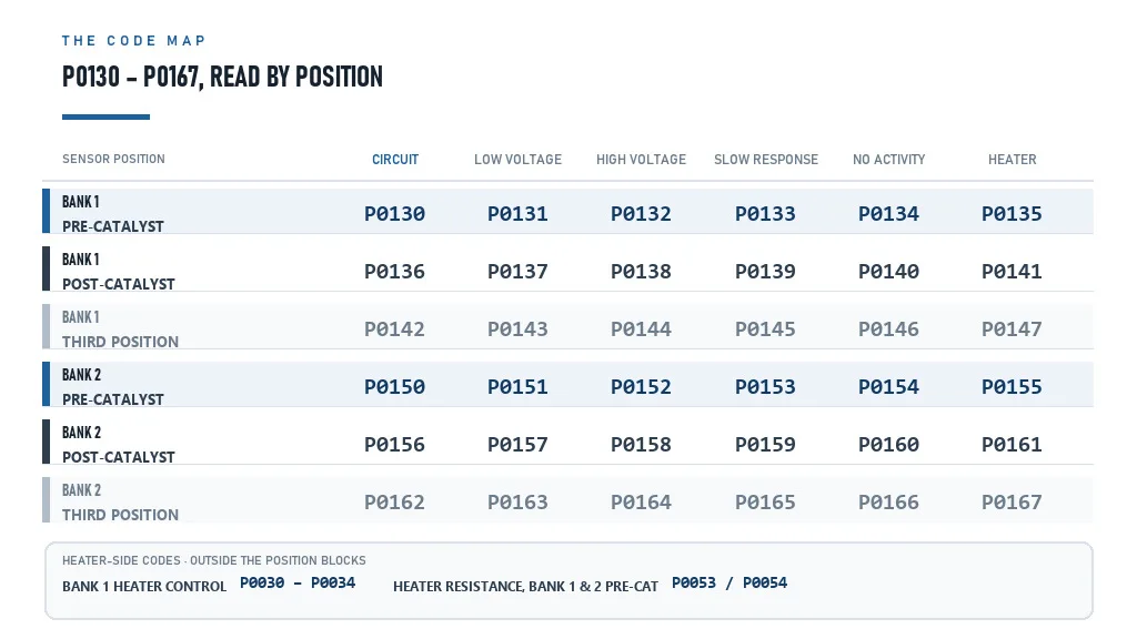 Eight sensor positions, one repeating fault sequence. Reading the code group first tells you which physical sensor is at fault, before any vehicle lookup begins.
3.3 The heater-side codes
Heater faults arrive in two forms, and the difference affects what you ship.
The P0030 to P0034 group and the P0053 and P0054 codes describe the heater control circuit and the heater's resistance. Because the heater draws current through a fuse, a relay, and a section of harness before it reaches the sensor, a fault reported here is not automatically a sensor fault [3]. A technician who replaces a sensor without checking the circuit has a reasonable chance of seeing the same code return.
The P0135, P0141, P0155 and P0161 codes sit inside the position blocks and describe a heater fault attributed to that sensor [3]. In practice most jobs resolve with the sensor, but the diagnostic order still starts with the circuit, and a distributor who says so out loud is giving the workshop a reason to keep calling.
4. P0420: How a Healthy Converter Gets Condemned
P0420 is the code that turns a parts enquiry into a four-figure repair estimate, and it is the reason this article exists.
4.1 What the catalyst monitor actually measures
Modern vehicles are required to carry a sensor before and after the catalyst, and the two signals are monitored to determine catalyst efficiency, with a failure reported to the driver through the on-board diagnostics system [1].
The mechanism behind that monitoring is oxygen storage. A three-way converter contains ceria or ceria-zirconia, added specifically as an oxygen storage promoter, alongside the platinum, palladium and rhodium that do the catalytic work [2]. A healthy converter absorbs oxygen when the exhaust is lean and releases it when the exhaust is rich, which smooths the mixture swings reaching the catalyst bed and lets it reduce all three regulated pollutants.
That storage behaviour is visible in the signal. Because a working converter damps the swings, the post-catalyst sensor produces a comparatively steady signal while the pre-catalyst sensor continues to switch continuously. When storage capacity declines, the post-catalyst signal begins to mirror the pre-catalyst one, and the monitor concludes that efficiency has fallen below threshold [1]. That conclusion is what P0420 reports on bank 1, with P0430 covering bank 2 [3].
A converter needs roughly 400°C to work effectively, which is why converters are mounted close to the engine or split into small pre-catalyst units immediately after the manifold [2]. It is also why an over-rich exhaust does damage: unburned fuel burns in the converter rather than in the cylinder, and the resulting heat shortens the substrate's life.
4.2 Three paths to a false P0420
The monitor reaches its verdict by comparing two signals. Anything that distorts either signal can produce the code on a converter that still stores oxygen correctly.
| Path to a false P0420 | Mechanism | What resolves the question |
|---|---|---|
| Aged or contaminated pre-catalyst sensor | The upstream signal is the reference the monitor compares against, and a lazy sensor distorts the comparison | Measure the sensor's response to an induced mixture change before judging the converter |
| Exhaust leak ahead of the post-catalyst sensor | Outside air reaches the downstream sensor and lifts its oxygen reading | Inspect and pressure-test the exhaust ahead of the sensor |
| Slow-responding post-catalyst sensor | A sensor that has stopped reacting looks similar to a converter that has stopped working | Compare the two signals directly rather than reading the code alone |
Contamination has documented causes. A sensor can degrade through normal aging, through leaded fuel, or through fuel contaminated with silicones or silicates, and those routes are also the documented paths from sensor failure to catalytic converter damage and expensive repairs [1].
The practical warning is in the third row. A sensor that has stopped responding produces a flat, quiet signal that a monitor can read as evidence of a converter doing its job, or as evidence of a converter that has failed, depending on which direction the drift runs. A code reader cannot tell those apart. Only a signal comparison can.
4.3 The diagnostic order that protects the customer's money
The order follows cost. The sensor is the least expensive candidate, the exhaust inspection costs labour only, and the converter is the expensive conclusion.
- Confirm the upstream sensor responds. Induce a mixture change and watch whether the signal moves as it should.
- Check the exhaust ahead of the downstream sensor. A leak admits air and corrupts the comparison.
- Compare pre-catalyst and post-catalyst signals. A converter with usable oxygen storage damps the post-catalyst signal while the pre-catalyst signal keeps switching.
- Only then judge the converter.
A distributor who can walk a workshop through those four steps in one message is doing something no catalogue does. The commercial outcome is not a smaller order in every case. It is an order that arrives with the workshop's confidence attached, and the trust is what produces the repeat purchase.
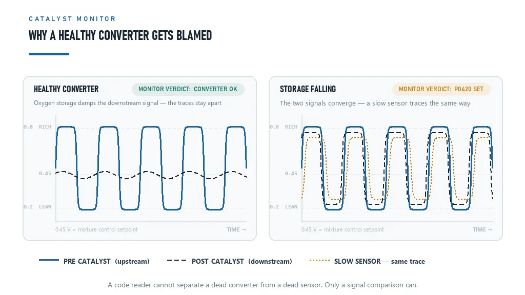 Left: a converter holding oxygen storage damps the post-catalyst signal. Right: when storage falls, the two signals converge and the monitor sets P0420. A drifting sensor can imitate the right-hand picture.
Fact: KEHO's oxygen sensor line covers both pre-catalyst and post-catalyst positions, including applications such as the BMW 3 Series E90 316i under OEM number 11787569968, with OEM number, vehicle model, year and displacement cross-verified before shipment (per company data).
5. What a Failing Sensor Does to the Rest of the Vehicle
A sensor fault is rarely contained to the sensor, and the reason is feedback.
Under light load the engine runs in closed loop: the control unit adjusts fuelling and expects to see a corresponding change in the oxygen sensor's response [1]. That loop is what keeps the mixture oscillating tightly around the stoichiometric point where a three-way catalyst can reduce all three regulated pollutants at once.
When the sensor stops reporting usefully, the loop breaks. The control unit loses its feedback and falls back on default behaviour, and the mixture drifts. In practice it drifts rich more often than lean, because default strategies err toward protecting the engine.
Rich running is where the damage happens. Unburned fuel leaves the cylinder and burns inside the converter rather than in the combustion chamber, which overheats the substrate, and prolonged rich operation can destroy a converter outright [1]. A converter is an expensive part with precious metals in it, and the sensor that failed to prevent its destruction costs a fraction of the replacement.
Lean running is not harmless either. Excess air raises combustion chamber temperatures, and at ultra-lean ratios the mixture can turn into misfires, with the associated loss of power and further converter risk [1].
The same mechanism is why the misfire monitor exists in the first place, and the reasoning is worth keeping next to this one. Unburned fuel and air reaching the converter is the hazard both monitors are built to prevent, whether the cause is a cylinder that stopped firing or a sensor that stopped reporting. The misfire diagnostic codes guide covers the first case from the ignition side.
For a distributor, the argument to give a workshop is short. The sensor is the inexpensive part that protects the expensive one, and a sensor replaced on a response complaint costs far less than a converter replaced after the sensor was ignored.
6. The Fuel Trim Layer: P0171, P0174, P0172 and P0175
Four codes in this neighbourhood are not sensor codes at all, and confusing them with sensor faults is how a wrong part gets quoted.
P0171 and P0174 report a system too lean on bank 1 and bank 2. P0172 and P0175 report a system too rich on the same banks [3]. All four are mixture codes, and they are computed from the oxygen sensor's feedback rather than read off the sensor's own circuit.
That distinction creates a diagnostic fork worth memorising.
- A trim code arriving alongside a response code. When P0171 appears with P0133, the mixture complaint and the slow-response complaint are describing the same object, and the sensor is the leading candidate.
- A trim code arriving alone, with a sensor that responds normally. Here the mixture is genuinely wrong, and the cause is upstream of the sensor: unmetered air entering through a leaking intake gasket or vacuum line, or a fuel delivery shortfall from a weak pump or a clogged injector. Replacing a sensor in this situation changes nothing, and the code returns.
The second case is why a distributor's technical support desk is worth more than a price list. A customer who buys a sensor, fits it, and sees the light come back does not blame the diagnosis. They blame the part. The fuel injector buying guide covers the fuel side of that fork.
There is also a failure-mode link worth flagging to customers. An engine running rich because of a real fuelling fault damages a converter the same way a failed sensor does, and a converter damaged that way produces P0420 later. Fixing the mixture fault is not optional once P0420 appears.
7. Failure Modes, and What They Leave Behind on the Part
Sensor codes describe electrical conditions, but the underlying failures leave physical evidence. Knowing which signature belongs to which code family is what lets a distributor sound like they have opened the part themselves.
| Failure mode | Code signature | Physical evidence |
|---|---|---|
| Heater open or out of range | P0135, P0141, P0155, P0161, P0053, P0054 | Often no visible damage; the sensor looks new and never reaches operating temperature |
| Sensing element aging | P0133 and P0153 response codes | Discoloured probe, eroded or partially blocked protection tube |
| Silicone or silicate contamination | Response and activity codes, sometimes voltage codes | Deposits on the probe and tube, often traced to a coolant or sealant source |
| Lead contamination | Response codes, with converter codes arriving later | Deposits on the probe, and a converter that fails early [1] |
| Signal bias | P0131 and P0132 voltage codes | Nothing visible on the part; the fault is in the element or its reference air path |
| Open signal circuit | P0134 no-activity codes | Frequently a harness or connector fault rather than a sensor fault |
| Case-ground fault | A range of codes depending on design | Specific to three-wire sensors that use the metal case as signal ground [1] |
Two rows deserve follow-up in conversation with a workshop.
The first is the heater row. A heater failure usually leaves a part that looks serviceable, which is why customers sometimes push back on the diagnosis. The explanation that lands is that the heater is what gets the element to roughly 316°C shortly after start-up [1], so a failed heater means the sensor is blind for the first minutes of every journey, even though the part looks fine on a bench.
The second is the no-activity row. P0134 can describe a dead sensor or a broken wire, and the diagnosis should establish which before a part is sold [3]. A distributor who asks for a resistance reading at the sensor connector separates the two cases in under a minute.
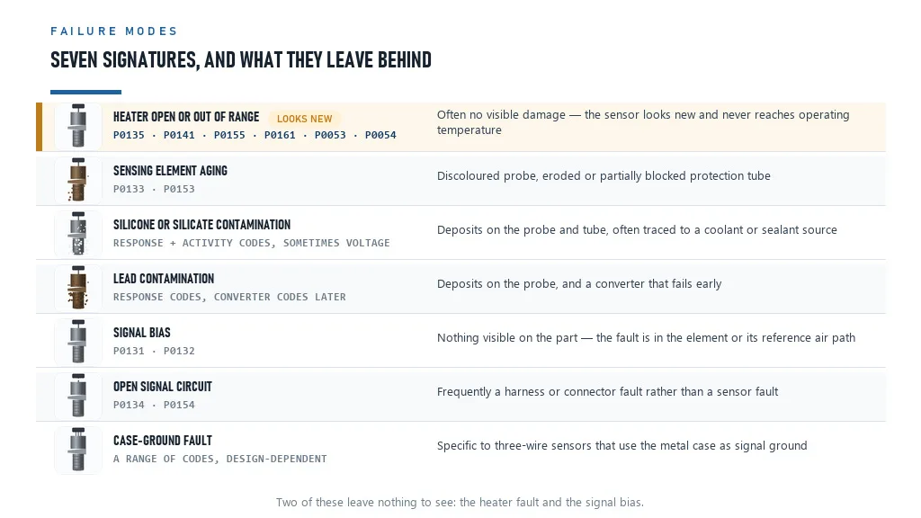 Seven failure modes, seven code signatures, and the physical evidence each one leaves. The heater row is the one customers argue about, because a failed heater leaves a part that still looks new.
Fact: KEHO holds 50,000+ SKUs, dispatches in-stock items within 48 hours, ships standard orders in 15-25 days, and backs parts with a 12-24 month warranty (per company data).
8. Building a Stock Plan by Code Family
The stock plan follows the code structure, not the vehicle list. Read the table by position and fault type, then apply your own market's fleet mix on top.
| Code family | First-pull part | Weighting logic |
|---|---|---|
| P0135, P0141, P0155, P0161 heater faults on any position | The exact sensor for that position | Highest velocity: a heater fault resolves to the assembly with no alternative diagnosis to chase |
| P0030 to P0034, P0053, P0054 heater control and resistance | The sensor, after the fuse and circuit are checked | Same part as above, but the circuit check comes first |
| P0133, P0153 slow response, pre-catalyst | Pre-catalyst sensor | Second highest: a response fault on a control sensor produces drivability complaints |
| P0134, P0154 no activity | Pre-catalyst or post-catalyst sensor, position-dependent | Check the harness before shipping, then supply the sensor |
| P0130 to P0132, P0150 to P0152 voltage codes | The sensor for that position | Confirm the harness is intact first; these codes also appear with genuine mixture faults |
| P0136 to P0141, P0156 to P0161 post-catalyst faults | Post-catalyst sensor | Lower urgency for the driver, because a monitoring fault is quieter than a control fault |
| P0420, P0430 converter efficiency | No sensor by default | Supply a sensor only when the response check fails, and say so in writing |
| P0171, P0174, P0172, P0175 mixture codes | No sensor by default | These are mixture codes; send the diagnostic fork instead of a part |
Three rules follow from the table.
Cover positions, not just engines. A catalogue that lists one oxygen sensor per engine leaves the post-catalyst position uncovered, and post-catalyst faults are exactly where a workshop needs the fastest possible answer, because the customer is already expecting bad news. Carry both positions for the engine families you stock, and keep the position mapping next to the OEM number.
Keep the wire count and connector in the data. A heated four-wire sensor dominates modern fleets, while older vehicles use unheated one and two-wire designs, and three-wire designs appear where the case serves as signal ground [1]. Wire count is a fitment field, not a footnote.
Treat P0420 as a technical support conversation. This is the one line in the table where the right answer is often no sensor and no converter. Handing a workshop the four-step order in section 4.3 builds more loyalty than any discount on a converter you cannot supply anyway.
9. Supplier Checks for an Oxygen Sensor Line
Sensor faults are diagnosed electrically, so the quality questions are electrical too. Asking about them in the right language is what separates a serious factory visit from a price negotiation.
| Check | What to ask | Red flag |
|---|---|---|
| Heater specification | "What are the heater resistance range and tolerance, and how is it tested per unit?" | No published range, or a range wide enough to cover any element |
| Response verification | "Do you test response time on a bench, or only continuity?" | Continuity testing described as full testing |
| Connector and wire count | "Are the connector, pin layout and wire count identical to the original for each application?" | "It fits most applications" |
| Reference air path | "How is the reference air path protected from contamination?" | Cannot describe how the element breathes |
| Position coverage | "Which applications do you cover for both pre-catalyst and post-catalyst positions?" | Pre-catalyst coverage only |
| Applications data | "Will you supply the position and wire count with the OEM number?" | Number and photo only |
| Anti-counterfeit controls | "How do you prevent reboxed or refurbished units entering a new-unit shipment?" | No process described |
| Warranty terms | "What does the warranty cover, and does it apply to electrical faults found on installation?" | Terms apply only to visible damage |
The heater specification question is the one to lead with. A heater that reads out of tolerance when cold will pass a continuity test and still set a heater code, which is how a good-looking sensor generates a comeback. A supplier who can quote a resistance range and a per-unit test method has an actual process behind the part.
KEHO runs a four-stage quality control sequence across its lines, covering incoming material inspection, in-process checking, packaging verification and final shipment review before dispatch (per company documentation), and applies OEM number, model, year and displacement cross-verification as standard. The supplier vetting guide covers how to test that kind of claim on a factory visit.
10. FAQ: Oxygen Sensor Code Questions From Buyers
What does an oxygen sensor fault code mean?
An oxygen sensor code reports either a fault in the sensor's own circuit or a mixture condition the sensor has detected. Codes in the P0130 to P0167 range describe circuit problems such as low voltage, high voltage, slow response, no activity, or a heater fault, and the code number itself tells you which bank and which sensor position is involved. Codes such as P0171 or P0174 are mixture codes derived from sensor feedback rather than sensor faults, so a distributor should read the whole code list before deciding which part to quote.
What does P0420 mean and is it always the catalytic converter?
P0420 means the catalyst monitor has concluded that bank 1 converter efficiency has fallen below threshold. It does not always mean the converter has failed. The monitor reaches that conclusion by comparing the pre-catalyst and post-catalyst sensor signals, so anything that distorts either signal can produce the code: an aged or contaminated upstream sensor, an exhaust leak ahead of the downstream sensor, or a slow downstream sensor. Verify sensor response and exhaust integrity before quoting a converter.
What is the difference between P0130 and P0136?
Both are oxygen sensor circuit codes for bank 1, but they describe different sensors. P0130 covers the pre-catalyst sensor on bank 1, the one the engine control unit uses for fuel correction, while P0136 covers the post-catalyst sensor on the same bank, the one used to judge converter efficiency. The same six-code pattern repeats for each bank and position, so the group a code belongs to identifies the physical sensor on the vehicle.
What is P0135?
P0135 is a heater circuit fault on the bank 1 pre-catalyst oxygen sensor. It is one of the most common oxygen sensor codes because the heater is what brings the sensor up to its working temperature of roughly 316 degrees Celsius shortly after start-up, and a sensor that never reaches that temperature cannot report a usable mixture signal. The heater and the sensing element are built into the same assembly, so a heater fault is normally resolved by replacing the sensor itself.
Can a bad oxygen sensor cause a catalytic converter to fail?
It can contribute. Once a sensor stops reporting accurately, the engine control unit loses the feedback it uses to hold the mixture near stoichiometric, and operation drifts rich. Unburned fuel then burns inside the converter instead of in the cylinder, which raises its temperature and shortens its life. Aging, leaded fuel, and contamination by silicones or silicates are the documented routes by which sensor failure leads to converter damage and expensive repairs, which is why the sensor is the cheaper of the two parts to replace early.
How do I know which oxygen sensor to replace?
Read the code group rather than the vehicle model. The P0130 to P0167 range is organised by bank and sensor position, so a code identifies the exact sensor, and the offset within its six-code group tells you whether the fault is a circuit, voltage, response, activity, or heater problem. Confirm the position against the vehicle, then match the connector and wire count, since heated four-wire sensors dominate modern fleets while older vehicles used unheated one or two-wire designs.
11. Selling the Sensor Instead of the Converter
This code family is unusual in the aftermarket because the structure is legible. The number tells you which sensor and which kind of fault, the offset tells you what to expect on the part, and the heater codes tell you that most of the volume sits in one assembly at one position.
The exception is P0420, and the exception is the opportunity. The monitor that sets it compares two signals, so the code is evidence about a comparison rather than proof about a converter. A distributor who can hand a workshop the four-step check in section 4.3 is answering a question the scan tool cannot, and the answer protects the customer from a repair estimate that runs into four figures.
That is a slower way to sell a sensor, and a much better way to keep an account. The product-level detail behind those positions, including upstream and downstream differences and the three sensing technologies, sits in the oxygen sensor buying guide, and the signal-side faults that produce their own code families are covered in the crankshaft and camshaft position sensor guide.
If you want the code family mapping built against the applications you already stock, send us the engines you cover and we will return a position-by-position list with OEM number, wire count, connector and pre-catalyst or post-catalyst designation attached to each line. The oxygen sensor range is listed under oxygen sensors, related fuelling parts under fuel injectors, and signal-side sensors under crankshaft position sensors.
Sources
- Wikipedia contributors. "Oxygen sensor." Wikipedia. https://en.wikipedia.org/wiki/Oxygen_sensor - Zirconia element construction with platinum electrodes and the non-linear output behaviour, the 0.2 V lean, 0.8 V rich and 0.45 V setpoint voltages, the approximately 316°C working temperature and the role of the heater, the 1990 planar sensor and its faster start-up, wire counts for heated and unheated designs, the regulatory requirement for sensors before and after the catalyst and the use of pre-catalyst and post-catalyst signals to determine catalyst efficiency, closed-loop and open-loop operation, the 1976 introduction by Bosch with Volvo, and the documented routes from sensor failure to catalytic converter damage.
- Wikipedia contributors. "Catalytic converter." Wikipedia. https://en.wikipedia.org/wiki/Catalytic_converter - Ceria and ceria-zirconia as oxygen storage promoters in the washcoat, platinum, palladium and rhodium as the catalytic materials, the approximately 400°C operating temperature and the resulting placement of converters close to the engine, and lead as a catalyst poison that prompted its removal from automotive petrol.
- SAE International. "SAE J2012, Diagnostic Trouble Code Definitions." SAE Standards. https://www.sae.org/standards/content/j2012_201612/ - Standard defining generic powertrain diagnostic trouble codes, including the oxygen sensor code blocks P0130 to P0167 by bank and sensor position, the heater control and heater resistance codes, the catalyst efficiency codes P0420 and P0430, and the fuel trim codes P0171, P0172, P0174 and P0175.